You are going to make a set of drawings and models of a house designed in the 20th century. You will also be tested on your knowledge of ALL these houses. First, go to the library and research these projects:
LE CORBUSIER
Maison Curutchet, LaPlata, Argentina
House at Weissenhof, Stuttgart, Germany
Heidi Weber Pavilion, Zurich, Switzerland
Villa Shodan, Ahmedabad, India
RUDOLPH SCHINDLER
Lovell Beach House, Newport Beach, CA
MICHAEL GRAVES
Hanselman House, Ft-Wayne, IN
JOHN HEJDUK
Wall House
Bernstein House
RICHARD MEIER
Smith House, Darien, CT
Saltzman House, East Hampton, NY
PETER EISENMAN
House IV, Cornwall, CT
REM KOOLHAAS
Villa Dall’Ava, St-Cloud, Paris, France
LOUIS KAHN
Esherick House, Chestnut Hill, PA
Milam Residence, Jacksonville, FL
Choose one of these houses and collect everything you can about it from the library and the internet. Do an Avery Index search for periodicals on the structure. Make a binder of all the printouts and photocopies you get on the project.
Bring ALL of your research to class on Tuesday. We'll have a raffle of who gets to do what project based on who has the most research done.
07 February 2009
05 February 2009
Class Schedule for Thursday, February 5th
If your TA seems clueless to this post then call them over and have them read it at the beginning of class. Point out to them that they should check their emails before class. You know all they do is party and daaaaaance while you all slave away and work your fingers to the bone.
Today you are going to pin-up your studio's work in a logical pattern like this: Three printouts side by side- on the left, a very early version of what they were doing (EXno.4 or EXno.5), in the middle the last one they did (EXno.8), and now the final one (EXno.9).
Make sure your work is separate from your classmates and the threesome can be discerned easily because...
For the first hour of class you will rotate over to review a section that you have not ever reviewed with (Lindsay and John or Adrianna and Sonya should not swap sections between themselves). Critique it and look at how the work developed. Is it a progressive transformation? Are they using the rules as conveyed? Which ones are working best? Each student claims one that is most like their own work and then, once they've claimed that work, they will be that person and will tell that work's story to their classmates. When there are fewer projects in the studio you are going to than there are people in your section double up.
For the last hour of class go through each of these projects (with each author mute) and get the studio to explain the apparent narrative in the work. What thematic devices can you discern in the work? What conceptual, intentional, parti, indexical, "big idea" , narrative device, way of working, organizational devices, systematic ways of working, etc. etc. are evident or apparent in each project. This is critical to discern as you begin to transform these things into another site and format. You have to start telling stories through what you see.
04 February 2009
EXno.9: The Last One
Refine what you've been doing up to this point in the semester into one last version. Print it out full scale and have it ready to talk about at the beginning of class.
30 January 2009
EXno.8: 50/50 and 20/80
Using the work to date as the source material make two new schemes that engage the whole of the 12" by 12" site on 14" by 14" paper. Mine the previous exercises (the source) for qualities and potentials to bring forward in the work to complete these two exercises (the current projects). Where possible just adjust the composition parametrically (changing proportions of parts while holding the developing relationships) rather than recomposing. The two challenges are:
EXno.8a: alter the ongoing work so that there is a balance of approximatly 50/50 of black and white space on the surface of the site. (In this there are equal parts of black and white.)
EXno.8b: alter the ongoing work so that there is a balance of approximately 20/80 of black to white space on the surface of the site. (In this white is the predominant spatial form).
Use regulating lines generated by the edges of every shape on the page. Think about how the schemes address the five organizational rules:
a) spatial hierarchy - an arrangement or classification of things according to relative importance
b) constants and variables - a series of regular and familiar clues, cues, signals, datum points, or reference points that add up to a framework, thematic matrix, armature, or formal structure within which difference (variables) work as the options and choices that create opportunities for thematic elaboration within the standardized framework of constants
c) spatial precincts and zones - enclosed or clearly defined areas differentiated at a scale beyond single defined or contained spaces and occurring throughout the site
d) zone, component and spatial articulation - constructed through the employment and control of butt joints; lap joints; dado joints; and reveals (gaps) throughout the site (formerly identified as "jointure")
e) economy of means - do more with less; prune; cut back to only essential to define a space
Have these printed, joined, and pinned up along with EX.no.7a on your studio wall at the beginning of class. We will introduce your precedent assignment on Tuesday and will not work on this stuff between Tuesday and Thursday to get that other work started.
28 January 2009
EXno.7 : Regulating Lines
Have these two variations (EXno.7a and EXno.7b) printed out (full size, no tape) and hung on the wall with the most relevant three of your ten last EXno.6 edits at the beginning of class.
Now, we are giving up the original underlying grid. We are also now completely giving up in the transition from movement to space. We'll start translating the spatial relationships you are making into a narrative of construction ("a big idea"), as we did as a group with a few different examples in class on Tuesday. Your placement of shapes on the 12 by 12 site will now generate its own grid by projecting regulating lines.
Procedure:
1) Review your last ten edits in EXno.6. Consider the ideas that we discussed and examples. Your work should be engaging the whole area of the site with an hierarchy of spaces comprised of black shapes, white spaces between them, composite black shapes, and composite mixtures defining and containing space.
2) In Form•Z and on the old grid sketch out a new edition of your work.
3) On a layer in Form•Z that is different from the one the black shapes and hatches are on, project from every edge of each shape a very thin black line to the edges of your 12 by 12 site.
4) Reconsider what you've done by turning off your your hatches and studying what you see. Make notes and printout this layout for your own reference.
5) Reconsider what you've done by turning off your your hatches AND the black boundary lines of the shapes and study what you see. Make notes and printout this layout for your own reference.
6) Adjust the current black shapes and their regulating lines to improve and clarify the spatial qualities of your work. Consolidate closely related regulating lines and their requisite shape edges when they seem to be redundant. Adjust to clarify jointure between parts, between spaces, and between composite forms. Adjust to clarify precincts and zones of space that associate across the site and throughout the shapes you are using.
All of this is still simply making use of intentional and crafty difference between white and black.
7) Printout two versions of your resulting exercise on full size 14 by 14 paper (2 sheets with an invisible joint). The first version (EXno.7a) should have the black shapes and the requisite regulating lines emanating from them. The second version (EXno.7b) should have the black shapes turned off so that all is printed are the regulating lines on the sheet.
25 January 2009
Sheet Joints
Tape is banned from putting the sheets together from here on out. The craft with tape is just too bad. The result is that your intentions are not clear because the craft is not good. That joint should be invisible. EXno.6 requires no joining. EXno.7 (due Thursday) will require two sheets printed and combined. Nothing using tape to combine the sheets will be accepted. Projects with visible joints will not be reviewed or assessed (a "0" for the exercise).
The best way to do this is to align the two sheets on your cutting mat and firmly tape them down in the correct relationship. Using an Xacto knife and a metal straight edge, cut down the overlapping joint so that both sheets are cut at the appropriate location. (Be very careful not to cut yourself.) Then, using RUBBER CEMENT and a third sheet as backing, glue the sheets butted up to each other. Ask your TA about this technique on Tuesday if that doesn't make sense. It makes no sense to put the effort into this work and then make it look unreadable through slap dash craft. You should be making work that lies flat on the wall and displays your intentions when pinned up. We are going to be much more clear now about what is acceptable in submissions.
The art supply store RENDR at 26th and Boston has Rubber Cement, unless you've all bought it all.
24 January 2009
EXno.6: 10 Variations
Using the feedback you got from the last class meeting make 10 new variations on your ongoing work. How much variation you take should be based on how to manage the maximum amount of development and change in your project. Questions to ask while you develop this project at this juncture are:
a) Am I creating Hierarchy throughout the whole site? (SITE=14 by 14 page)
b) Am I developing a "Space Grammar" that engages the variabilities of the given black shapes (overall scale, shape orientation, the changeable parametric proportions of the shapes, the spatial characteristics of the shape, the spatial relationships the shapes can have between each other)
c) In representing the motion in the film piece am I constructing 2-D graphical space and spaces across the whole of the SITE?
AT THE BEGINNING OF CLASS on Tuesday have all ten printed out each on ONE sheet of 8.5 by14 paper so that you end up with 10 sheets of paper to pin up on Tuesday. Label each sheet EXno.6-01, EXno.6-02, EXno.6-03...through EXNo.6-10.
We will no longer review any work that is not crafted to the standards explained and outlined so far- no visible tape or sheet joint line (not an issue on this exercise), solid black shapes, no more grey on the sheet, light grid lines that do not interfere with the reading of the project, only the exercise number on the front of every sheet IN HELVETICA OR ARIAL. Name on the back
18 January 2009
EXno4
Due printed and ready to pin-up at the beginning of class on Tuesday. Only work that is printed and pinned up by the beginning of class will be reviewed.
Make sure you save each exercise as a separate file. You will be turning in each file for assessment in a few weeks.
Do a new composition that builds off what you've started and the comments made during the last class. Use DIFFERENCES to make your analysis of the movement in the Playtime Clip intelligible. Make INTENTIONS clear. CONTROL the whole 12 by 12 area delineated on the SURFACE through your work.
One thing to change on the pin-up sheet: Remove the text block with your name, leaving only the exercise number on the front of the sheet. Start printing your names on the back of each pin-up sheet.
15 January 2009
Printing 14 by 14 on Your Printers
 The goal is to print on two side by side sheets of 8.5 by 14 and tape them together. The image above shows you how to manipulate all the dialog boxes. The text below tells you how to do the same thing. "Mr. Lamb of God" figured all this out and told me about it. Give your props to him for figuring it out and remembering what was done.
Go to the pull down menu "FILE" (where you get "OPEN" and "SAVE") and select "PLOT/PRINT SETUP". In that dialog box set the scale to 1=1, "extents", no "frame", and check yes for "overlap paper".
Then click on "Page Setup". "Format For" your printer.
Then select "Custom Page Sizes..." and in there make a new paper size called 1412, make the "Page Size" 8.5 by 14, and zero out the "printer margins".
Then you are ready to print. Check your print with "Page Preview" back in the "PLOT/PRINT SETUP" menu box. Do everything you can to save all these settings so the process is automated.
Make sure you have excellent craft on putting the two sheets together with tape. The seam should not be seen before the work is seen. It should not be in the way of seeing what you've designed.
You should print at least five progress prints that are just "fit to page" as you proceed on each exercise.
If you plotted these it would cost you at least $4 per plot. With your printer (and lots of prints) your costs will be much, much less. We'll plot later in the semester but we'll use the print lab only when it is absolutely necessary.
If that doesn't work then you can try this method.
13 January 2009
Form•Z Introductory Notes
(Everything needed in FmZ for the first 1/3rd of the semester)
Topological Levels
points, segments, faces, elements, groups
self, one copy, multi-copy, continuous copy
Ordinates
picker
snaps / ortho
key shortcuts / preferences
layers
Object Makers
line, rectangle, parallel line, point, text
Object Modifiers
trim, break, join, connect, text edit, hatch
Object Translators
move, (copy), rotate, scale, scale x-y, mirror
Attribute Modifiers
line type / line weight, color, layer
EXno.2 - in class exercise for Tuesday

We find its easier to learn in editing than it is in inventing. The format of this drawing is the format you'll use throughout the first 1/3 of the semester. The title block, layout, scale, and means of printing for this drawing will be the same on everything you do until we draw a new format in four weeks. Everything you do will be submitted three ways: In Paper, In a Form•Z file, and in a PDF file. Your TA will show you how to do all these things well.
The standard sheet is 14"x14". There is a 1" buffer on the sheet surrounding a 12" by 12" work area that is centered on the sheet. The common zone stretches from side to side (X direction) down the middle of the work area. The common zone is .75" tall. In the X direction the work area is broken into 14 equal sections each marked by a dark grey thin vertical line that stretches across the work area. Each of these major X sections is divided into 4 equal minor parts. The work are is bifurcated about the common area into two equal sides in the Y direction. Each of these sides is broken down into a minor (.625" tall) section at the bottom and the remainder is equally divided between two major elements of each character.
Certain Form•Z files are provided. Download the 1412 drafting preferences and point the app towards it after starting it. Download the 1412_MPStudio_EXno2.fmz file. This drawing is the base for this exercise.
Due printed and assembled on your section's wall by the end of studio class today.
The exercise is a team project. Everyone in your section needs this done before the end of class.
09 January 2009
In Class on Tuesday, Jan 13
It was assumed that you all would secure your lockers in the room. Make sure your locker locks up and that you can tie it to a desk or a buddy's locker. People will steal things. Those of you who left stuff in the room, we hid your stuff behind the grey metal lockers in the room. Those of you that are thieves- there are cameras all over the buildings and digital records. If you are found thieving then you'll be out of the university. Don't even look like you're stealing. I recommend a cheap cable lock and drilling a hole in the rubbermaid type tubs to run the cable through.
You'll need everything- computer, printer, "stuff"- in class on Tuesday. You'll work mostly with your TAs on Tuesday so come to class ready to work or to be sent away so we can work without you gumming our work up. Those of you who have temporary computer issues can go use the computer lab- if it is free.
We'll fix any Form•Z issues you all may have at the start of class.
Ex#1: Texting Movement
First, download and read the class syllabus and familiarize yourselves with it. On Tuesday ask your TA any questions you have about the syllabus.
The real exercise, as they all will, is available as a pdf for download to the left. This entry is just the background material referenced for the exercise.
The movies are linked to the left as well. There is a zip file containing all three versions for those who want it on their machines.
Our first major question for the semester is: How is movement (four-dimensional) or the image of movement (three-dimensional) translated into two-dimensions?
References:
To see other ways of notating, tracing or “witnessing” a scene, ways that have already been devised, consider (research) the methods of:
• The Choreographer
Labanotation:
• The Painter
"Nude Descending a Staircase" by Marcel Duchamp
• Time-Motion Study
Frank Gilbreath Motion Study
Therbligs
• Photographic Locomotion Study
E.J. Marey
Eadweard Muybridge
08 January 2009
Course Objectives
• Above everything else this studio is going to be about doing. The way in which design is learned is through experiencing; through the carrying out of a process. The instructor’s role in the studio is more of guide than teacher. It’s more Socratic (responsive) than Aristotelian (indoctrinal) and that means that this course is going to be fueled by your questions and constant questioning. In design we question by working. This is called Practice.
• The other thing the studio will focus on is understanding what it is that we’ve done. The way in which understanding the design (a noun rather than a verb) is learned is by another direction of questioning: the development of a discourse. The Socratic process is reversed here and the instructor will ask the questions. It’s like jeopardy: the instructor gives the answer and the student looks to find the question in the work. Once the student is aware of the question the work becomes “Informed.” The work invokes discourse and the more informed the work, the higher the level of the discourse. Discursive questioning of the work is called Theory.
We’ll come back to talk about discourse at a later date.
07 January 2009
First Day of this Class
All of our classes will be held on the fourth floor (rooms 401 to 404).
Fir the first day of class you should bring enough sheets of loose 8.5 by 14 paper and your writing implements to take notes. You will have an exercise due Tuesday using Form•Z drafting.
Everything you need for this class should be in the studio by the beginning of class on Tuesday.
See you at 10h00 or 12h30.
13 May 2008


05 May 2008
Cleaning
All of Your Stuff is Going to Leave the Building Monday or Tuesday
To dispose of your sand and sand box:
a) Remove all the protruding nails and string from the box. Put the nails and string in the trash. Brian has already put a nail through the bottom of his shoe.
b) Using a small bucket or trash can remove the sand from the box. Do not put sand in the large trash cans or anywhere else. Clean up anything you spill. The sand makes the floor very slippery. Take care.
c) Using a cart or a dolly take the sand to the courtyard level and add it to the pile that is started against the concrete wall on the north side of the courtyard.
d) Stack the box on the fourth floor with the rest of the boxes that are staying OR remove it from the university campus.
To dispose of all your paper in the building:
a) Take down all paper from the walls and windows. Pick up all paper on the floor.
b) Take your goods out to the dumpster on the courtyard level or remove the paper from the campus.
To dispose of the box lid:
A pile of box tops has been started in the fourth floor studio. Put yours there or remove it from the university campus.
To dispose of your wire model and blocks:
a) Remove the blocks from the model.
b) Remove the model and / or blocks from any base to which they may be attached.
c) Dispose of the wire model and cardboard, foamcore, or foam blocks in the dumpster outside on courtyard level.
d) A pile of wood blocks has been started in the fourth year studios. Put them there or remove them from the campus.
Work that has been held over the course of the semester is now in a "Corral" that we've made in the 4th floor studio. You can take anything in the "Corral". Material on the tables where Marti and Brian are working just outside the "Corral" is not to be removed. You can photograh it but it cannot be removed. It is going on display. You'll see it in the fall when you return. If you are not going to take care fo the work in the "Corral" then please leave it for us to display or dispose of. Anything left in the "Corral" after Tuesday at 8PM will be disposed of.
Thanks for a fantastic semester...
Stay tuned...
30 April 2008
File Folder
Here it is ::
ARCH1412_XXX.zip
Unzip this file and the folder will appear magically on your desktop! Amazing...
All files must be illustrator (ai) files, or pdf's, you cannot include dwg's or dxf's. Lets keep it real. Image files can include jpeg, pdf, and or tiff.
Thank you and have a wonderful summer if we do not see you!
We will be writing more accolades soon so keep yourself posted...
Filling

So how do you fill in elements in Illustrator without changing lines?
1. Select the group that you want to render, say all of the columns from the big bar, or the floor slabs. 2. Go to the live paint bucket and click again. 3. De-select 4. Re-select the object group 5. Go to the fill button and fill with what color you want to fill with, say a gray. 6. Then go to the Object pull down menu and click on expand, when you expand a dialog box will appear, de-select the fill and the stroke box leaving the object box the only one checked. 7. Go back to the Object pull down menu and ungroup your selected elements twice. 8 Then select one of the filled parts. 9. Go to the Select pull down and click on Same, followed by selecting Same Fill Color, it will select the all of the fill color and not the line. Here you are separating fill from line. This gives you so many more drawing and notational opportunities. 10. While all of the fill is still selected, go to the layer window. Make a new layer. Then go back to the fill that is still selected and find the color box one the right side of the layer window. Grab and drag it to the new layer. Now you fill and line are in two separate layers, and you can change the opacity of your fill while leaving your line alone.
28 April 2008
Rest of Semester Schedule for ARCH1412
Tuesday, April 29th
In Studio: Review wire models and drawings with your TA. By Thursday, May 1st at 9:00AM, have all your logs, drawings, and photographs printed and on your wall in an orderly manner. Finish wall space to look like Lauren’s section (in the studio on the northwest wall).
In Lecture: Review for the final submission and exam (see exam on May 6th below). Fill out course Faculty Questionnaire. The faculty course questionnaire is about MARTI and BRIAN as faculty, not about the performance of the TAs except in relation to how MARTI and BRIAN managed them as they taught the course.
IMPORTANT!!! EVERYTHING ABOUT THE SANDBOX PROJECT MUST REMAIN PINNED UP AND CLEARLY ATTRIBUTED TO YOU AT YOUR SANDBOX IN YOUR ASSIGNED SECTION FROM THURSDAY, MAY 1st at 9:00AM UNTIL MONDAY MAY 5th at 7:00PM.
Thursday, May 1st at 9:00AM
All print and physical Sandbox work is pinned up and ready to review for grade. Grading begins. Photography begins as we photograph all the completed boxes and all the “A” level work form Bounding space left in the studio at this time. All our photos wil be put up on a designated server space (see course web page for details).
All Sandbox digital work is burned to a CD (clearly marked in “sharpie” with your section # and name) and delivered to your TA for review. On the website there is a folder hierarchy and file naming system that you will use to submit your work in on the CD you will burn. Work not submitted properly will result in the Sandbox project receiving a grade of 0. Your TA will explain where to turn in your CD. No CD = 0 grade.
Leave everything in the studio until you are told we are done with your section. Otherwise, start clearing out on Monday, May 5th, at 2:00PM.
Monday, May 5th, at 2:00PM.
Begin clearing out all material you used in this course. See exam instructions below.
Tuesday, May 6th
Your Exam: Between Monday, May 5th at 2:00PM and Tuesday, May 6th at 7:00PM you will properly dispose of your sand (at a location to be determined) at the courtyard level of the architecture building. YOU WILL NOT DUMP SAND IN A TRASH CAN OR ANYWHERE ELSE IN THE BUILDING. IF you are caught doing so you will fail this course for academic dishonesty. It is absolutely unfair to the custodial staff to have to lug your sand out of the building. You will remove all work from your wall and remove it from the building or place it in a proper trash can. You will search the building for any other ARCH1412 coursework that is attributed to you and you will remove it. You will either take your sandbox away from the campus or you will leave it empty in room 401 for us to use as part of a larger project that will be done during May.
YOUR EXAM GRADE WILL be 12 of 12 points if you:
a) Take your sand to the designated location for disposal.
b) Either place your sandbox empty in the middle of room 401 or remove it from the campus.
a) Clean your designated sandbox space in the building.
b) Remove any ARCH1412 work from the building that could be attributed to you.
c) Submit your properly formatted CD to your TA by the deadline.
YOUR EXAM GRADE will be 0 of 12 points if we:
a) Do not see your sandbox workspace full of your work and ready to grade by Thursday, May 1st at 9:00AM.
b) Find you’ve removed any part of your sandbox work before Monday, May 5th, at 2:00PM.
c) Find any ARCH1412 work after Monday, May 5th, at 2:00PM in the building that can be attributed to you by recognition or written name.
d) Find your sandbox sand in your box or anywhere else in the building but the designated dumping location on the courtyard level after Monday, May 5th, at 2:00PM
e) Find your sandbox anywhere but empty and stacked up in the middle of Room 401 after Monday, May 5th, at 2:00PM.
f) Find your CD not submitted to your TA or improperly formatted after Monday, May 5th, at 2:00PM.
23 April 2008
Drawing Examples

To construct this drawing, I shaded the surface a very light gray to further distinguish surface from object. You may do this, but it is not a requirement.

Draw your 13 boxes and place them in your grid. To do this I actually turned off the surface layer and used the original "21 by 21 Regulating Lines" layer to accurately place them in space. To draw the boxes I simply drew a 2 by 2 box and moved a copy up 10 inches and connected the lines. After you are done studying the boxes in space and carefully creating your path space and your subsequent place space, turn the surface back on and the regulating grid off to see what you have.

Draw the path space and the place space that your boxes create. To do this you will need to lock all layers and create a new layer labeled Forms. You will be using the top box edge to regulate and draw what spaces were created from these objects. Turn on the Drop Lines Layer and select the edges of the lines where the intersections of the form are created (see above). Copy those lines and move them to a new layer (you can refer to the attached drawing at the end of this post), turn off the Drop Lines layer and change the linetype of the new linetype. You will have the tops and the sides after these steps. To create the North and South and East and West connections use the Work Layer Profile layers and select the lines that intersect and follow the bottom edge of your form and copy and paste that into a new layer. Now turn off your box object layer and view the forms created by the boxes with the wire surface.

Turn off all surface layers and print your final forms of space.
Here is the ai file :: 1412_Sp08_XXX_Sandbox_100ptWork_1to1scale_Space.ai
Here is a dwg file :: 1412_Sp08_XXX_Sandbox_100ptWork_1to1scale_Space.dwg
Here is a dxf file :: 1412_Sp08_XXX_Sandbox_100ptWork_1to1scale_Space.dxf
(take note of the new layers in the drawing)
22 April 2008
17 April 2008
Baroque Wireframe
l’unanime pli - one CONTINUOUS surface, fabric, -scape, or -scope.
Gilles Deleuze in THE FOLD: Leibniz and the Baroque
 considerations
These continuous surfaces appeared as ontologically quantified and studied conditions in the 17th and 18th centuries by philosophers and mathematicians such as Leibniz and Descartes (Calculus is a mathematics based on the potential of a continuous fold and topological notions of space and measure). These studies paralleled and influenced the development of Baroque architecture- an architecture responsible to the ability to project within complex surface. The importance of the fold (including conceptual folding and material folds) may have emerged with the Baroque but it has remained an issue in artists (such as Paul Klee), poets (such as Mallarme), and musicians (Berlioz). In the last 20 years folding in architecture has become a common thread in many academic and professional studios. This renaissance of the fold as a key intellectual and technological development in architectural production is chronicled across four texts. In 1988 the philosopher Gilles Deleuze published the book THE FOLD: Leibniz and the Baroque and refocused the importance of the fold in critical thinking and practice. In the same year Avrum Stroll wrote of the notion of geometric descriptions rooted in everyday geometries of surface in his book SURFACES. In 1993, FOLDING IN ARCHITECTURE, a collection of essays edited by Greg Lynn was published. In 1995 Bernard Cache published EARTH MOVES: the Furnishing of Territory, in 2003 Sophia Vyzoviti published FOLDING ARCHITECTURE: Spatial, Structural, and Organizational Diagrams. These five sometimes opaque and difficult texts make up a backbone of teaching through folding.
The exercise returns to wire. We’ll use wire to execute this exercise. You’ll need just over 220 feet of it. You can use the wire you already have on hand. The most successful work overall this semester was done with wire. Reconsider the ways you developed in working with wire and let the metal craft of the project be a major part of your projections.
method
• Take four high resolution digital photographs, using a one strong light, of the existing surface in your sandbox. The light should be evenly dispersed and create intense interior shadows. Print it out and pin these images up each as a 6”x6” black and white print on 8.5 bt 11 inch (letter) white paper on your wall. Put your name and section # on the back of each sheet. Name the .tif photo files “1412_sp08_XXX_ExF_Photo0X.tif” where XXX is your initials and Photo0X is the photo number (1 through 3).
• Study the graphics and database you’ve developed to complete the new 441 point drawing of the sand and hose surface. Discern the dominant inflections and facets described in the drawing. Write this down or sketch it out for your reference.
 • Translate the spatial and superficial contents of the 441 drawing into a well crafted 121 by 121 mesh made of wire. This should be a simplified material translation of a full scale model of the sand surface projected in your 441 drawing- nothing else. The strands of wire should be arranged in a 2 inch by 2 inch grid with a perimeter of 20 inches by 20 inches. There should be nothing but mesh- do not make external elements to prop or hold the mesh.

This wire mesh model will become the site for the rest of the semester’s design work. Prepare it well and consider the intersections and specificity of your material design. You will be asked to add cubic and cylindrical elements to this model as we progress.
Gilles Deleuze in THE FOLD: Leibniz and the Baroque
 considerations
These continuous surfaces appeared as ontologically quantified and studied conditions in the 17th and 18th centuries by philosophers and mathematicians such as Leibniz and Descartes (Calculus is a mathematics based on the potential of a continuous fold and topological notions of space and measure). These studies paralleled and influenced the development of Baroque architecture- an architecture responsible to the ability to project within complex surface. The importance of the fold (including conceptual folding and material folds) may have emerged with the Baroque but it has remained an issue in artists (such as Paul Klee), poets (such as Mallarme), and musicians (Berlioz). In the last 20 years folding in architecture has become a common thread in many academic and professional studios. This renaissance of the fold as a key intellectual and technological development in architectural production is chronicled across four texts. In 1988 the philosopher Gilles Deleuze published the book THE FOLD: Leibniz and the Baroque and refocused the importance of the fold in critical thinking and practice. In the same year Avrum Stroll wrote of the notion of geometric descriptions rooted in everyday geometries of surface in his book SURFACES. In 1993, FOLDING IN ARCHITECTURE, a collection of essays edited by Greg Lynn was published. In 1995 Bernard Cache published EARTH MOVES: the Furnishing of Territory, in 2003 Sophia Vyzoviti published FOLDING ARCHITECTURE: Spatial, Structural, and Organizational Diagrams. These five sometimes opaque and difficult texts make up a backbone of teaching through folding.
The exercise returns to wire. We’ll use wire to execute this exercise. You’ll need just over 220 feet of it. You can use the wire you already have on hand. The most successful work overall this semester was done with wire. Reconsider the ways you developed in working with wire and let the metal craft of the project be a major part of your projections.
method
• Take four high resolution digital photographs, using a one strong light, of the existing surface in your sandbox. The light should be evenly dispersed and create intense interior shadows. Print it out and pin these images up each as a 6”x6” black and white print on 8.5 bt 11 inch (letter) white paper on your wall. Put your name and section # on the back of each sheet. Name the .tif photo files “1412_sp08_XXX_ExF_Photo0X.tif” where XXX is your initials and Photo0X is the photo number (1 through 3).
• Study the graphics and database you’ve developed to complete the new 441 point drawing of the sand and hose surface. Discern the dominant inflections and facets described in the drawing. Write this down or sketch it out for your reference.
 • Translate the spatial and superficial contents of the 441 drawing into a well crafted 121 by 121 mesh made of wire. This should be a simplified material translation of a full scale model of the sand surface projected in your 441 drawing- nothing else. The strands of wire should be arranged in a 2 inch by 2 inch grid with a perimeter of 20 inches by 20 inches. There should be nothing but mesh- do not make external elements to prop or hold the mesh.
This wire mesh model will become the site for the rest of the semester’s design work. Prepare it well and consider the intersections and specificity of your material design. You will be asked to add cubic and cylindrical elements to this model as we progress.
16 April 2008
15 April 2008
Retaining the Sand Surface
For Thursday you need to rework the surface in your box using dry sand, nylon, and string. Today we saw the nylons being used as retaining walls, bags, and hammocks. The hammock technique is not working because although we are using two materials, the sand is still one singular surface and we should read it as such. You can use the hammock method, but it should be partially submerged, this will still read as a single surface. The "hammock" when suspended in air reads as two surfaces. Exploit your box, use the string and the nails on the box, they are there for several reasons. The surface should be a translation of what was in your box either in version one or in version two. The second surface you had in your box was due las Thursday, this is the preferable surface to translate with the hose. As a reminder the assignment last week was to change the view or frame and recreate the surface again and draw it again. The assignment for today was to directly interpret the surface of the sand without the use of water. We are looking for a correlation between surfaces. So using the nylon and the string how can you manipulate your sand to look like your prior surface? Some of you are having trouble because your sand is not drying. Either put it in front of a window or transport the wet sand to the outdoors and replace your sand with dry sand. Dispose of your sand responsibly!
The new surface is due on Thursday along with a drawing including all of the 441 points of the grid. This is a big assignment so you should start right away. Take a picture of the final surface and print it as a 6x6 for Thursday, the sand should be smooth, make it pretty. The drawing instructions are below:
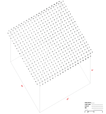
Goal:
To log & construct a plan oblique graphical representation of the surface of your dry sand plus pantyhose sandbox using only lines. The drawing is of the sand and not the pantyhose.
Procedure:
1) Download & print the pdf file "1412_Sp08_XXX_SandBox_441ptLog.pdf" on 11 by 17 paper in landscape format & "fit to print". The outcome should look close to this: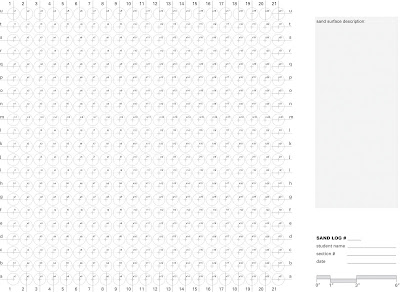
4) We recommend you use Illustrator for this assignment if you have it but you can do the work in a CAD application too. These instructions will try to remain "neutral" but the CAD files may have some distortions and layer changes in them. All work was done in Illustrator.
For CAD: Download & open the DWG file "1412_Sp08_XXX_Sandbox_441ptWork.dwg".
Also for CAD: Download & open the DXF file "1412_Sp08_XXX_Sandbox_441ptWork.dxf".
For Illustrator: Download & open the AI file "1412_Sp08_XXX_Sandbox_441ptWork.ai".
You should have fewer problems than before with this drawing:
5) With the file open get familiar with all the layers, lineweights, & linetypes. You will draw in the work layers. The layers have been arranged so that the top three are your work, the next few are the most needed references, & the last few layers are more obscure and non-print references. You should use the layers you did for the 100 pt drawing.
6) Turn on the work layer "Depth Lines". On that layer we've started an example for you to review. You should be familiar with the method so you should just erase the sample. From each grid intersection draw a fine, grayed short dashed line down from the point as long as the sand is deep in the box. You may want to create more layers within the depth lines so you will have Depth A through Depth U. And if you want to be safe create layers for the numbered portions as well, Depth 1 through Depth 21. Since there are 441 points the endpoints will be hard to see. You can turn layers on and off it need be.
7) Turn on the work layer "WorkLayer-ProfileLines_East to West". Along each "east-west" row of depth lines connect the bottom end points of each line with a medium, solid , & black line segment. Turn one layer on at a time and just draw that row, rinse rather and repeat while moving from a to u.
8) Turn on the work layer "WorkLayer-ProfileLines_North to South". On that layer we've started an example for you to review. Once familiar with the method you should erase this sample. Along each "north-south" row of depth lines connect the bottom end points of each line with a medium, solid , & black line segment. Turn one layer on at a time and just draw that row, rinse rather and repeat while moving from 1 to 21.
9) Now turn off the depth lines & the notation so that you have the box, the sand surface, the top level intersections, & the title block. Be consistent with your prior prints.
10) Print it 1/2 scale on the OCE, or one of the large format printers in the print bureau. Pin this drawing up over your sandbox. Again it is important to be consistent with your prior prints.
11) Save the file as a pdf file named "1412_Sp08_XXX_Sandbox_441ptWork.pdf".
This is due on Thursday. You will be marked for completion.
The new surface is due on Thursday along with a drawing including all of the 441 points of the grid. This is a big assignment so you should start right away. Take a picture of the final surface and print it as a 6x6 for Thursday, the sand should be smooth, make it pretty. The drawing instructions are below:
Goal:
To log & construct a plan oblique graphical representation of the surface of your dry sand plus pantyhose sandbox using only lines. The drawing is of the sand and not the pantyhose.
Procedure:
1) Download & print the pdf file "1412_Sp08_XXX_SandBox_441ptLog.pdf" on 11 by 17 paper in landscape format & "fit to print". The outcome should look close to this:

2) First write a description of the surface(s) in your sandbox in superficial & formal terms in the given space on the printed out log sheet. Use the terms we've started talking about in everyday geometries. Describe hierarchies, alignments, & other relationships / differences in surface quality. Describe the construction of the nylon and what forces are being performed to manipulate the surface of the sand.
3) Wrap the string around every nail to create the complete measuring grid with string. Now in your sandbox measure the height of the 441 pts indicated on the given graph & log each of them in pencil in the corresponding circle on your printed out log sheet. Keep this paper log. Pin it up over your box. It will be a part of your grade.
3) Wrap the string around every nail to create the complete measuring grid with string. Now in your sandbox measure the height of the 441 pts indicated on the given graph & log each of them in pencil in the corresponding circle on your printed out log sheet. Keep this paper log. Pin it up over your box. It will be a part of your grade.
4) We recommend you use Illustrator for this assignment if you have it but you can do the work in a CAD application too. These instructions will try to remain "neutral" but the CAD files may have some distortions and layer changes in them. All work was done in Illustrator.
For CAD: Download & open the DWG file "1412_Sp08_XXX_Sandbox_441ptWork.dwg".
Also for CAD: Download & open the DXF file "1412_Sp08_XXX_Sandbox_441ptWork.dxf".
For Illustrator: Download & open the AI file "1412_Sp08_XXX_Sandbox_441ptWork.ai".
You should have fewer problems than before with this drawing:

5) With the file open get familiar with all the layers, lineweights, & linetypes. You will draw in the work layers. The layers have been arranged so that the top three are your work, the next few are the most needed references, & the last few layers are more obscure and non-print references. You should use the layers you did for the 100 pt drawing.
6) Turn on the work layer "Depth Lines". On that layer we've started an example for you to review. You should be familiar with the method so you should just erase the sample. From each grid intersection draw a fine, grayed short dashed line down from the point as long as the sand is deep in the box. You may want to create more layers within the depth lines so you will have Depth A through Depth U. And if you want to be safe create layers for the numbered portions as well, Depth 1 through Depth 21. Since there are 441 points the endpoints will be hard to see. You can turn layers on and off it need be.
7) Turn on the work layer "WorkLayer-ProfileLines_East to West". Along each "east-west" row of depth lines connect the bottom end points of each line with a medium, solid , & black line segment. Turn one layer on at a time and just draw that row, rinse rather and repeat while moving from a to u.
8) Turn on the work layer "WorkLayer-ProfileLines_North to South". On that layer we've started an example for you to review. Once familiar with the method you should erase this sample. Along each "north-south" row of depth lines connect the bottom end points of each line with a medium, solid , & black line segment. Turn one layer on at a time and just draw that row, rinse rather and repeat while moving from 1 to 21.
9) Now turn off the depth lines & the notation so that you have the box, the sand surface, the top level intersections, & the title block. Be consistent with your prior prints.
10) Print it 1/2 scale on the OCE, or one of the large format printers in the print bureau. Pin this drawing up over your sandbox. Again it is important to be consistent with your prior prints.
11) Save the file as a pdf file named "1412_Sp08_XXX_Sandbox_441ptWork.pdf".
This is due on Thursday. You will be marked for completion.
08 April 2008
Pop Assessment
Today we will start lecture class at 6:30PM. This is to allow you a few minutes to address the following matter:
As many of you have noticed there is an incredible disparity between what some of you have accomplished to date on the current project and what some of you have not started and or finished. The disparity is too great. Something has to be done. The number who are keeping up have to be acknowledged and those trailing have to be identified and held to a standard of completion. You all should now have:
a) A finished sandbox with the interior painted white, 50% of the interior filled with sand, a perimeter register of nails and stenciled notation, and your name neatly indicated somewhere on the box. This box should be set up and work in progress in the area in teh building designated for your studio. (Exercise Sandbox A)
b) A "ventilated" (sliced with a knife) image from a domestic interior that has been over-sprayed. A frame should have been affixed on this over-sprayed image that encloses the square on the ventilation you've translated into the sandbox. This model should be pinned or taped up over your sandbox. (Exercise Sandbox B)
c) A translation into the surface of the sandbox of this framed location on your ventilation. (Exercise Sandbox D)
d) A printed out large format drawing as specified in my post on the class webpage. This should be posted above the sandbox. (Exercise Sandbox C & E)
Today, during the lecture course, the TAs will make a grade of what you have done so far on the sandbox project. Below is the grading sheet they will use. This grade will for 5 points of your total semester's 100 points. That leaves the grade for the 20 last studio points and the 12 points left for the final exam.
 Please take the first half hour of the lecture class to make sure your space is organized, your name is there, and your work is set up in an orderly manner. We'll start our presentation at 6:30 (18h30) sharp.
The TAs will have this assessment ready for you at the end of class.
Fixed Drawings
Fixed files ::
So here is a dxf : 1412_Sp08_Sandbox_100ptWork_1to1scale_1.dxf
and here is a dwg file : 1412_Sp08_Sandbox_100ptWork_1to1scale_1.dwg
One will work better than the other. If you are using Autocad please try both one will work better than the other, you want the one that transfers lineweights as well as text. This should work now! If you are using Illustrator you should not have any troubles with the files that were posted previously.
XXX is representative of your initials...MLG, BTR, ect. ect. When you are finished downloading re-save the file as 1412_Sp08_XXX_Sandbox_100ptWork.
Have fun....
When you print the large drawing print it at 1/2 scale not full scale on a 24 x 24 sheet. If you had troubles printing this morning do not worry, just make sure it is pinned up on your wall before tonights class. We will be checking and grading so make sure it is there.
Presentations
On Wednesday at 5PM Jennifer Siegel of The Office of Mobile Architecture in Los Angeles will be presenting her work. You all should go. We'll be bringing her through the studios sometime Wednesday. Greet her and talk to her. She does really amazing work and will be impressed by yours if you explain yourselves. She has hired TTU architecture students in the past.
On Thursday at 3PM Chris Taylor, a candidate for the college's Chair of Instruction position, will make a presentation. He is interested in coming to TTU from UT to teach and lead the school. Check him out and put in your two cents on this candidacy. He'll be coming through your studios that morning. Talk to him and show him that students here don't have a boot up their butt like they do at UT.
On Thursday at 3PM Chris Taylor, a candidate for the college's Chair of Instruction position, will make a presentation. He is interested in coming to TTU from UT to teach and lead the school. Check him out and put in your two cents on this candidacy. He'll be coming through your studios that morning. Talk to him and show him that students here don't have a boot up their butt like they do at UT.
Class Today
You all will be working in class today. If you do not take advantage of the oportunity we'll not give it again. Keep quiet, work hard, and use your time and TA wisely. Be prepared to work.
07 April 2008
10th Floor Exhibit
We've put up a show of select projects on the 10th floor.
Go see it.
BOUNDING SPACE
DORM ROOM MODELS, INDEXES, & DIAGRAMS
Featured Students:
Jordan Berta
William Cotton
Shane Logains
Peter Longoria
Celeste Martinez
Preston Neumann
Armando Olivera
Jigga Patel
CURRENT WORK FROM ARCH1412 STUDIO ONE : GOTTSCH & REX
DORM ROOM MODELS, INDEXES, & DIAGRAMS
Featured Students:
Jordan Berta
William Cotton
Shane Logains
Peter Longoria
Celeste Martinez
Preston Neumann
Armando Olivera
Jigga Patel
CURRENT WORK FROM ARCH1412 STUDIO ONE : GOTTSCH & REX
Go see it.
1 to 1 Scale Drawing
The drawing that is posted below is at a 1/2 scale so the 20" dimension is at 10 inches so your measurements will be off by 1/2. Some of you are already have discovered this problem.
So here is the Illustrator file : 1412_Sp08_XXX_Sandbox_100ptWork_1to1scale.ai
and here is the dwg file : 1412_Sp08_XXX_Sandbox_100ptWork_1to1scale.dwg
XXX is representative of your initials...MLG, BTR, ect. ect.
Have fun....
So here is the Illustrator file : 1412_Sp08_XXX_Sandbox_100ptWork_1to1scale.ai
and here is the dwg file : 1412_Sp08_XXX_Sandbox_100ptWork_1to1scale.dwg
XXX is representative of your initials...MLG, BTR, ect. ect.
Have fun....
06 April 2008
Sandbox Drawing #1
 clickable image
To log & construct a plan oblique graphical representation of the surface of your sandbox using only lines.
Procedure:
1) Download & print the pdf file "1412_Sp08_XXX_SandBox_100ptLog.pdf" on 11 by 17 paper in landscape format & "fit to print". The outcome should look close to this:
 clickable image
2) First write a description of the surface(s) in your sandbox in superficial & formal terms in the given space on the printed out log sheet. Use the terms we've started talking about in everyday geometries. Describe hierarchies, alignments, & other relationships / differences in surface quality.
3) In your sandbox measure the height of the 100 pts indicated on the given graph & log each of them in pencil in the corresponding circle on your printed out log sheet. Keep this paper log. Pin it up over your box. It will be a part of your grade.
3) In your sandbox measure the height of the 100 pts indicated on the given graph & log each of them in pencil in the corresponding circle on your printed out log sheet. Keep this paper log. Pin it up over your box. It will be a part of your grade.
4) We recommend you use Illustrator for this assignment if you have it but you can do the work in a CAD application too. These instructions will try to remain "neutral" but the CAD files may have some distortions and layer changes in them. All work was done in Illustrator.
For CAD: Download & open the DWG file "1412_Sp08_XXX_Sandbox_100ptWork.dwg".
For Illustrator: Download & open the AI file "1412_Sp08_XXX_Sandbox_100ptWork.ai".
5) With the file open get familiar with all the layers, lineweights, & linetypes. You will draw in the work layers. The layers have been arranged so that the top three are your work, the next few are the most needed references, & the last few layers are more obscure and non-print references. Here is an image of what layers are in the file in Illustrator. (If your CAD file has messed up layers you should move things to match this set-up.):
 clickable image
6) Turn on the work layer "Depth Lines". On that layer we've started an example for you to review. Once familiar with the method you should erase this sample. From each grid intersection draw a fine, grayed short dashed line down from the point as long as the sand is deep in the box. Here's the way this should look:

7) Turn on the work layer "WorkLayer-ProfileLines_North to South". On that layer we've started an example for you to review. Once familiar with the method you should erase this sample. Along each "east-west" row of depth lines connect the bottom end points of each line with a medium, solid , & black line segment. Here's the way this should look:
 7) Turn on the work layer "WorkLayer-ProfileLines_North to South". On that layer we've started an example for you to review. Once familiar with the method you should erase this sample. Along each "north-south" row of depth lines connect the bottom end points of each line with a medium, solid , & black line segment. Here's the way this should look:
8) You're done drawing! Turn on all the work layers to see it this way:
 9) Now turn off the depth lines & the notation so that you have the box, the sand surface, the top level intersections, & the title block. It will look like this:
 10) Print it full scale on the OCE, or one of the large format printers in the print bureau. Pin this drawing up over your sandbox. Your TA can help you with printing during class.
11) Save the file as a pdf file named "1412_Sp08_XXX_Sandbox_100ptWork.pdf". Your TA will show you how to do this in class on Tuesday.
This is due by the end of class on Tuesday. You will be marked for completion.
01 April 2008
Drawing the Sandbox Log (amended)
 This drawing should be drawn in CAD or Illustrator or both, if you are brave, at 1:1 scale drawing. Please reference the link below or the image above. Step by step instructions:
a) The first lines to draft are a grid of regulating lines spaced at 1" intervals in both the horizontal and vertical directions on your screen. These lines should not be any different from the hand drawn construction lines you used in your bounding space drawings. They will be very thin 50% gray lines.
b) Draft a 20" by 20" box in a black medium thick line, like the cut lines you drew in your last assignment, to indicate the extents of the sandbox.
c) Draft thick 25% (light) gray short crosses at the regulating line intersections to notate your points.
d) Represent the nails on the box periphery at every 1" as a medium line weight in 50% gray line. This line should be 1-1/2" long and project 1/2" into the sandbox.
e) Draft the circles. The circles should be a .45" radius, black and one line weight thicker than the regulating lines, and centered on the regulating line intersections.
f) Register notation about the perimeter of the box reading left to right as 1 through 21 and a though u from bottom to top on all edges of the box delineation. The font should be bold Helvetica or Arial and be 10pt.
g) Register notation housed in the upper right quadrant of each circle that indicates the particular location in bold 6pt Helvetica or Arial.
You can look at the illustrator file here.
A half scale printout of this drawing on 11" by 17" (or two halves on 8.5" by 11 sheets neatly and discretely taped together) is due at the beginning of class on Tuesday April 1st.
31 March 2008
Sandbox Template
v.2 of the templates is coming out Monday around noon. After Tuesday's class you should paint the templates on the side of your box and set all the nails. Then the box will be complete. The templates have been sent to the laser cutter. They'll work as follows:


30 March 2008
Due Tuesday
Emily Andersen, who made the regulating line drawings of Freeways that are posted below, is working in China on a project for her firm. She dedicated to all of you this photo she took in a mannequin factory. She said it looked like the photos of our studio. For Tuesday: you will have a sandbox with the interior painted white, filled with sand, and the domestic ventilation translated into the surface of the sand; you will have a version of your sandbox log printed out; and you will have the domestic ventilation you've chosen to translate.
See the exercise handouts linked to the left.
It seems you've learned trades already this year.
You all could take up careers shaping mannequins and building cat boxes.
 For Tuesday: you will have a sandbox with the interior painted white, filled with sand, and the domestic ventilation translated into the surface of the sand; you will have a version of your sandbox log printed out; and you will have the domestic ventilation you've chosen to translate.
See the exercise handouts linked to the left.
It seems you've learned trades already this year.
You all could take up careers shaping mannequins and building cat boxes.
26 March 2008
Materials List
1 stick of 2 by 12 (1.5" by 11.25") by 8' long #1 grade SPF or equivalent
2 pieces of 24 by 24 (nominal) by 3/8" (critical) cheap plywood (BC Fir at PanTex)
200' of white or black kite string (no neons)
Flat white paint to cover the interior of the box with two coats
12 #10 countersink wood screws 2.5" long
2.6 cubic feet of dry fine granule sand (w/ no added binders or debris)
96- 2d (penny) nails (1" long)
A basic wooden ruler
Ordering Plywood
PanTex Wood
116 E 42nd St
Lubbock, TX 79404
(806) 747-2561
This company will take an order for 3/8" by 8' by 4' plywood sheets over the phone with payment by credit card ($21.90 per sheet for "BC Fir") and they will deliver the load to the building for you. You can get 8 people's wood out of one sheet if you're buying one piece per person OR if you all want a lid (recommended) you can get four people out of one sheet. One of you has to call in the order and tell them to deliver to the architecture building. They are prompt and you will have it in the shop without a hassle. GO!
24 March 2008
You should be prepared
We are going to have a clean-up/shop day tomorrow. We will have teams assigned to do different projects around the room. We will have a couple sections on desk cleaning detail, a couple sections cleaning chairs, one section may even mop! It took 46 trash cans to clean that room, so yes you all made quite a mess, so now is the time to finish the cleaning. We promise not to get you too dirty, but you should dress appropriately for class tomorrow. Be ready!
You should also buy a 2" x 12" x 8' piece of lumber and bring it to class tomorrow if possible or we will arrange some trucks to travel to Home Depot or Pan-Tex to retrieve our needed lumber. We will have a couple groups working on building boxes tomorrow. The 2" x 12" will vary in length and price. At Home Depot this piece is 12' long and 17.97 without tax. Stores will sell a 2" x 12" anywhere from 8' in length to 12' in length. You need a piece that is at least 8', do not worry about getting one longer than this. You really need four 24 inch pieces to build your box. We will discuss the box you will be using for the remaining part of the semester at length first thing tomorrow. The interior dimension of the box will be 20" x 20" x 10".
See you tomorrow....
15 March 2008
Michel Rojkind
 Michel Rojkind, a leading young designer from Mexico City, visited your studios on Thursday this past week. He had only great things to say about the collective spirit and energy you've accumulated in that studio. Marti and I are going to have a tough time shoveling it all out of there.
Your efforts have challenged a lot of the students in the upper years, have made a few people upset, and has made some of the teachers you'll have in the next few years very excited and positive about teaching you. You've made yourselves known as a class that will meet a challenge. You've made yourselves known as a class that knows how to go about making things.
We had no idea that this would be so messy. We have our work cut out for us.
13 March 2008


12 March 2008
Hand-In Number 2 Guidelines
Anything left in the room over the break will be thrown away. Any tool, past drawing, model, or backpack will be tossed into the trash. We need to clear and clean the studio over the spring break. If you need to leave something in the studio put it in a locker and secure it with a lock.
There will be a marked section location in the hall way for you to turn in your projects. You will turn in your cubic wire model, fiat wire model, section drawings, and your two foam models. Projects not left in the appropriate location will get a zero.
Format for turning in your projects will be as follows : Each of your models should be submitted with a piece of drafting tape affixed on its bottom that clearly displays your name and your section number. No boxes, no bags just place them together, side by side. Your section drawing set should be held together with two small binder clips and then rolled. When you roll your drawings make sure to physically roll to the binder clips, do not start the roll with the binder clips. The roll of drawings should be fully protected by a tube, a piece of paper, or a plastic sleeve. Your name and section number should be clearly displayed on the outside of the roll. This roll will be placed with your models.
If you are turning the projects in tomorrow and not Friday at 8am, then you can just place it at the top of the lockers in the hallway.
08 March 2008
Reminder
It should be foamy in the studio :
Your order of operations for this assignment should be similar to the list below:
cut, glue, dry, sand, sand, sand, sand, sand, sand, sand, sand, spackle, dry, sand, paint, dry, sand, paint, dry, sand, paint, dry, sand, paint, dry, sand, paint, dry, sand, ect, ect. Remember to use two different kinds of sand paper, a medium grit, and a fine grit. The fine grit sand paper will make your model incredibly smooth.
You will have a variety of geometric situations in your foam models. The interstitial model will have some 90 degree angles, your fiat model may as well. A fine grit sanding block will aid you in this dilemma.
Remember, both your fiat model and your interstitial model are due on Thursday.
Here is a more specific operation list:
Glue with tacky glue.
Sand with a medium grit then followed by a fine grit sandpaper.
Spackle any major surface impurities and allow to dry. Then sand your result. You may need to repeat this two or three times.
Now you are ready to paint. You paint layers should be light, do not lather on the white, it will take longer to dry. Allow the layer to dry then sand with a fine grit sandpaper. Then paint again.
You will need to repeat this last step up to ten times.
The result: a beautiful white model as smooth as silk.
27 February 2008
Emily Andersen's Freeway Drawings
Emily is an architect in Manhattan. These drawings are formal and flow analysis from the first part of her design project for architecture integrated into freeway construction. Before she studied architecture she studied studio art and fashion.
Either way, these drawings demonstrate the kinds of connection, craft, and geometricization of a form that we're asking you to construct. They are the geometries of bona fide ribbons of concrete, not fiat blobs of where you occupy the room. The way that the drawing is systematized through graphics of arcs and circles, tangents and radii.


Either way, these drawings demonstrate the kinds of connection, craft, and geometricization of a form that we're asking you to construct. They are the geometries of bona fide ribbons of concrete, not fiat blobs of where you occupy the room. The way that the drawing is systematized through graphics of arcs and circles, tangents and radii.


Report on Test #1
The test was worth 12 of 100 semester points. With the 25 points for the first third of the studio you've now got 37 of your semester's points. By the time you return from Spring Break we'll have another 25 points graded for you over this current studio work.
Drop day is coming up. It is March 12th. We will notify you if we currently have concerns about your passing the class.
The average grade for Test #1 is very high. Many of you did quite well. There are a few people who got less than half the questions right. It seems as though either you did really well or you did quite bad with just a handful doing poorly.
The bonus was a drawing showing a Component set and Colorado is a state made up of only fiat boundaries.
I just told you some of the answers. We said there'd be no make-up test. If you did not make it to the test then the second test will count for 25 points of your grade. We'll just double the points you earn on that test. The second test will still be cheat sheet based but will include some readings, will still be all multiple choice, but not so easy- I'd expect.
Thanks for being so cooperative in taking the test and, for the most part, doing so well.
Subscribe to:
Posts (Atom)


.gif)