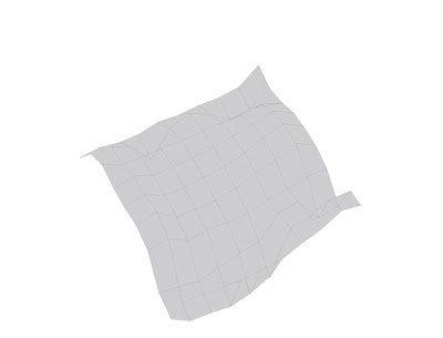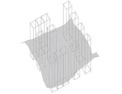
To construct this drawing, I shaded the surface a very light gray to further distinguish surface from object. You may do this, but it is not a requirement.

Draw your 13 boxes and place them in your grid. To do this I actually turned off the surface layer and used the original "21 by 21 Regulating Lines" layer to accurately place them in space. To draw the boxes I simply drew a 2 by 2 box and moved a copy up 10 inches and connected the lines. After you are done studying the boxes in space and carefully creating your path space and your subsequent place space, turn the surface back on and the regulating grid off to see what you have.

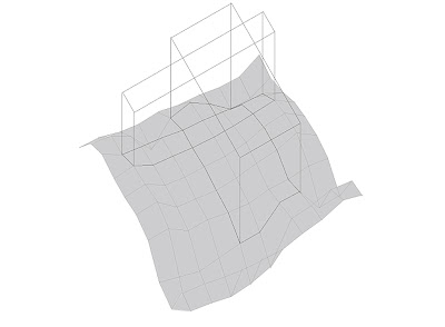
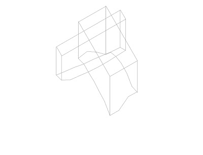
Draw the path space and the place space that your boxes create. To do this you will need to lock all layers and create a new layer labeled Forms. You will be using the top box edge to regulate and draw what spaces were created from these objects. Turn on the Drop Lines Layer and select the edges of the lines where the intersections of the form are created (see above). Copy those lines and move them to a new layer (you can refer to the attached drawing at the end of this post), turn off the Drop Lines layer and change the linetype of the new linetype. You will have the tops and the sides after these steps. To create the North and South and East and West connections use the Work Layer Profile layers and select the lines that intersect and follow the bottom edge of your form and copy and paste that into a new layer. Now turn off your box object layer and view the forms created by the boxes with the wire surface.

Turn off all surface layers and print your final forms of space.
Here is the ai file :: 1412_Sp08_XXX_Sandbox_100ptWork_1to1scale_Space.ai
Here is a dwg file :: 1412_Sp08_XXX_Sandbox_100ptWork_1to1scale_Space.dwg
Here is a dxf file :: 1412_Sp08_XXX_Sandbox_100ptWork_1to1scale_Space.dxf
(take note of the new layers in the drawing)


